System News:
hardware-linearisation
improved HV-noise for higher resolution in combination with large scan range
new scan modes (e.g. SGM)
List prices starting from 19.990 Euro
Datasheet
Our High-Speed AFM offers a wide Spectrum of Measurement Methods:
High resolution Contact mode
Students learn the principle of the laser deflection system and how to
adjust the system.They can take an image in contact mode and check the
difference between slow feedback speed (constant height mode) and fast
feedback speed (constant force mode).
With distance curves, they can calculate the sensitivity of the system
and
calculate the contact force used in the experiments.
High resolution Dynamic mode
For the daily use of AFM, the imaging in dynamic mode is more common
than
the contact mode, because tip and sample are spared.The
students learn the relation between force constant and resonance
frequency, repeat some knowledge about harmonic oscillating systems,
resonances and Q-factors and get introduced to the basics of lockin
amplification technique, which is used to evaluate the amplitudes and
phase shifts.In
the acquired images, material contrast can be obtained in the phase
image in addition to the topography.
Current-AFM Mode
Lateral force mode
Lateral force imaging
In contact mode, lateral forces are detectable and can be used to find
material contrast in inhomogeneous samples.
The experiment explains how LFM is working and the students learn to
understand, how to distinguish between topography-related signals and
material-related signals.
Force Spectroscopy
Kelvin Probe Force Microscopy
Kelvin Probe Force Microscopy (KPFM) is a technique that allows to detect work function differences
on surfaces as well as local charges. It has undergone a long development and there are many different
kind of KPFM operation modes known. All KPFM mode have in common, that an alternating plus a dc bias is
applied between tip and sample. The forces resulting from the alternating voltage are used to generate a
feedback signal that controls the value of the dc bias. Usually, a signal of a lockin amplifier is compensated
to zero with the KPFM feedback.
Two of the available Anfatec SPM controllers offer KPFM capability: the AMU2.6 controller type
offers it for lockin frequencies up to 1 MHz and the AMU2.9-HighSpeed controller version offers
it for frequencies up to 10 MHz. In both cases, the lockin card includes four independent 2-phase
lockin amplifiers. They can be configured in a way, that AM-KPFM, Side band KPFM on the 2nd cantilever
resonance or FM-KPFM experiments can be performed.
AM-KPFM image of an Al / silicon surface taken with a DEP01 cantilever with Pt coating.
Topography (left) and Surface Potentoal (right). The Al wire is buried into the silicon surface and
shows the more positive surface potential. The silicon is covered with a thin oxide laser and the surface
potential slightly decays in dependence on the distance from the Al edge.
Resonance enhanced FM-KPFM image of an Al / silicon surface taken with a DEP01 cantilever with Pt coating.
Topography (left) and Surface Potentoal (right). In comparison to the AM-KPFM image, the potential contrast
is better localized due to the side band detection. There are also more potential features visible on the Al
surface. The potential difference between Al and Si is measured with 190 mV.
Magnetic Force Microscopy (2nd trace imaging)
Magnetic Force Microscopy
In Magnetic Force Microscopy (MFM), each line of the images is taken twice: the first trace is used to
get the topography information. The 2nd trace is following the topography in a certain height of several
nm and mainly detects long range interactions, such as interactions caused by magnetic forces. MFM employs
cantilevers with a magnetic coating, usually CrCo coated silicon tips.
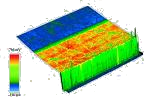
Topography (left) and MFM Amplitude (right) images of a Bruker reference sample for MFM. Image Size: 1.5 µm x 1.5 µm.
Topography (left) and MFM Phase (right) images of a Bruker reference sample for MFM. Image size: 40 �m x 40 �m.
Electrical Force Microscopy
The field of electrical force detection in AFM is very wide. Here,
we have selected a technique, where the electrical forces are
separated from the topography with modulated voltage applied between
tip and sample.
The students can go through some basic formulas and finally measure on
a
provided transistor structure capacitance differences caused by
different thicknesses of oxide layers.
EFM Mode (Single trace)
Topography FWD
EFM Signal 1st Harmonic FWD
EFM Signal 2nd Harmonic FWD
EFM Mode (Dual trace = Lift Mode)
Topography FWD
2nd Trace Amplitude FWD
2nd Trace Phase FWD
Nano-Lithography with script-language
Elastic Force Microscopy (Force Modulation Mode)
Optional Features
Vibration isolation table under the microscope
Hardware scanner linearisation (feed forward type)
Glass bell jar for acoustic protection
Additional cantilever packages and gratings
Enhanced LFM mode sensitivity (circular laser diode)
Additional LockIn amplifier for dynamic EFM or MFM
Implemented Kelvin feedback
Current amplifier for conductance AFM incl. power supply
SPIP - Scanning Probe Image Processor - with all customer specific modules from Imaging Metrology
2nd TFT monitor
Low noise laser module
Camera Specification
Camera Sensor
2592 x 1944 Pixel (5 MPixel)
Camera Sensor Type
CMOS color
Optical Sensor Dimensions
3.620 mm x 2.720 mm (4.53 mm diagonal)
Pixel Size
1.4 µm
Optical Resolution
< 4 µm
Pixel Resolution
500 nm
Field of View
1.3 mm x 1 mm
Filter
blue filter (for DNC laser suppression)
Sensor Interface and Power Supply
USB 2.0
controller for the fast Approach of Tip and Sample
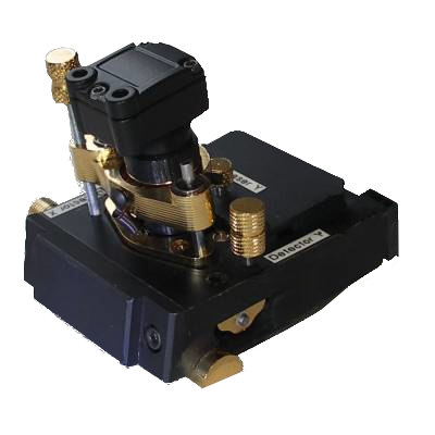
Image of the AFM head with the compact Top View camera design
and Sample Illumination
AFM-Head including a Top View USB-Camera and Sample Illumination
The USB-camera combines a 5 MPixel CMOS sensor and high resolution optics with low
a magnification. The resulting large field of view enables quick location of the area of
interest. An optical resolution below 4 µm ensures the visibility of small
structures. An implemented filter reduces the intensity of the back reflection of the
red DNC laser. Therefore, high quality images during scanning in non-contact mode is
possible.
Camera Images
Camera image of a the AFM cantilever above a TGF11 calibration grating with 10 µm pitch illuminated by a white LED.
Camera image of a calibration glass slide with 10 µm scale bar illuminated by a white LED.
Image of self-assembled 850 nm polystyrene spheres coated with silver. These grating-like structures refract visible light in different colors. The black spots correspond to silver islands.
Image of self-assembled layers of 350 nm polystyrene spheres coated with silver. Different layers (mono- or bilayer) give rise to different colors. The black spots consist of silver islands.
Image of a µmash NSC15 cantilever. The tip apex (pointing towards the camera) is shining red.
Image of a gold coated high-speed SU8 cantilever.
>
Illuminated by a white LED.
Illuminated by a green LED.
Illuminated by both, white and green LED.
Image of a monolayer of hexagonal packed self-assembled 850 nm polystyrene spheres coated with silver. These grating-like structures refract visible light in different colors depending on the layer orientation and the wavelength of the incident light.
The AFM-head comes with an off-axis sample illumination by two different LEDs on opposite sides. Depending on which LED is active, different sphere layer orientations are shining bright.